Aerial RF Measurement:
Why Networks Must Be Measured in 3DMisura RF aerea:
perché la rete va misurata in 3D
Mobile networks are planned in three dimensions, but they are almost always measured in two: along the roads a test vehicle can drive. Everything above the second floor — where antennas actually point, where fixed-wireless customers live, where drones will soon demand connectivity — is usually a guess. Aerial measurement closes that gap.
Le reti mobili si pianificano in tre dimensioni, ma si misurano quasi sempre in due: lungo le strade che un veicolo di test può percorrere. Tutto ciò che sta sopra il secondo piano — dove le antenne puntano davvero, dove vivono i clienti fixed-wireless, dove i droni chiederanno presto connettività — di solito è una stima. La misura aerea chiude quel varco.
The Vertical Blind SpotIl punto cieco verticale
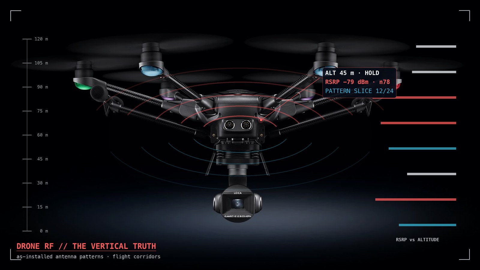
A sector antenna on a 30-metre tower with a few degrees of downtilt concentrates its energy in a lobe that first touches the ground hundreds of metres away. A drive test samples exactly that: the far, ground-level edge of the beam. The region between the antenna and that first touchdown — including the vertical face of every building in between — goes unmeasured. Complaints from a penthouse and a perfect drive test on the street below are not a contradiction: they are two different slices of the same three-dimensional field.
Historically the only way to sample that region was a tower climb or a crane — slow, expensive, and requiring a safety file for every visit. This is precisely the niche that UAV-based measurement fills: a drone reaches any point in the surrounding volume in minutes, repeatably, with centimetre-level positioning.
Un'antenna settoriale su un traliccio da 30 metri con qualche grado di downtilt concentra l'energia in un lobo che tocca terra per la prima volta a centinaia di metri. Un drive test campiona esattamente quello: il bordo lontano del fascio, a livello del suolo. La regione fra l'antenna e quel primo contatto — inclusa la facciata verticale di ogni edificio nel mezzo — resta non misurata. I reclami da un attico e un drive test perfetto sulla strada sottostante non sono una contraddizione: sono due fette diverse dello stesso campo tridimensionale.
Storicamente l'unico modo per campionare quella regione era una salita in quota o un'autogrù — lenta, costosa, con un fascicolo di sicurezza per ogni visita. È esattamente la nicchia che la misura con UAV riempie: un drone raggiunge qualsiasi punto del volume circostante in minuti, in modo ripetibile, con posizionamento centimetrico.
Antenna Patterns in the Real WorldI pattern d'antenna nel mondo reale
The radiation pattern on a datasheet was measured in an anechoic chamber. The pattern in the field is a different object: mounting brackets, the tower structure, nearby antennas, feeder losses and an installer's tilt error all reshape it. Flying a measured orbit around the antenna under test reconstructs the pattern as installed — revealing dead spots, overlapping beams between sectors, and physical channels in conflict. For a network engineer this is ground truth that no simulation can provide; for an operator it is the difference between guessing why a sector underperforms and seeing it.
Il diagramma di radiazione sul datasheet è stato misurato in camera anecoica. Il pattern sul campo è un oggetto diverso: staffe di montaggio, la struttura del traliccio, le antenne vicine, le perdite dei feeder e un errore di tilt dell'installatore lo rimodellano. Un'orbita misurata attorno all'antenna in prova ricostruisce il pattern come installato — rivelando dead spot, sovrapposizioni di fascio fra settori e canali fisici in conflitto. Per un ingegnere di rete è una verità di terreno che nessuna simulazione può dare; per un operatore è la differenza fra ipotizzare perché un settore rende poco e vederlo.
Who Needs Altitude DataA chi servono i dati in quota
- FWA operators — a fixed-wireless CPE lives on a facade or a roof, not on the street. Placement decisions deserve measurements at the actual height.
- High-rise coverage — upper-floor complaints can only be verified with upper-floor data.
- Drone corridors (BVLOS) — regulators increasingly ask what connectivity a corridor guarantees at 60 or 120 metres. Nobody has drive-tested the sky.
- Interference hunting — an interferer invisible at street level is often obvious from thirty metres up.
- Operatori FWA — una CPE fixed-wireless vive su una facciata o un tetto, non in strada. Le decisioni di posizionamento meritano misure alla quota reale.
- Copertura nei grattacieli — i reclami dai piani alti si verificano solo con dati dei piani alti.
- Corridoi per droni (BVLOS) — i regolatori chiedono sempre più spesso quale connettività un corridoio garantisca a 60 o 120 metri. Nessuno ha mai fatto drive test del cielo.
- Caccia alle interferenze — un interferente invisibile a livello strada è spesso evidente da trenta metri.
How a Drone Survey WorksCome funziona un rilievo con drone
The measurement payload can be a dedicated probe or — increasingly — a standard smartphone running measurement software: lighter, cheaper, and measuring the network exactly as a subscriber's device would. The mission alternates two geometries: orbits at constant radius around an antenna for pattern work, and vertical profiles — climbs at fixed horizontal position — for coverage-versus-altitude curves. Two practical constraints dominate mission design: wind tolerance (a survey platform must hold position with full payload in real wind, not just in the brochure) and data continuity — at altitude the phone may itself lose coverage, so measurements must buffer locally and sync later without loss.
Il payload di misura può essere una sonda dedicata o — sempre più spesso — uno smartphone standard con software di misura: più leggero, più economico, e misura la rete esattamente come il dispositivo di un abbonato. La missione alterna due geometrie: orbite a raggio costante attorno all'antenna per il lavoro sui pattern, e profili verticali — salite a posizione orizzontale fissa — per le curve copertura-quota. Due vincoli pratici dominano il progetto missione: la tolleranza al vento (una piattaforma da rilievo deve tenere la posizione a pieno payload con vento vero, non da brochure) e la continuità del dato — in quota il telefono stesso può perdere copertura, quindi le misure devono bufferizzare in locale e sincronizzare dopo, senza perdite.
Airborne Measurement with NEXTLa misura aerea con NEXT
NEXT flies exactly this configuration: a NEXT measurement phone mounted on the IDMS drone — stable with full payload in winds up to 15 m/s — capturing full RF metrics with 3D GNSS positions, buffered offline and delivered into the same NEXT Fusion tenant as your ground drive tests. Ground and air, one dataset, one map.
NEXT vola esattamente questa configurazione: un telefono di misura NEXT montato sul drone IDMS — stabile a pieno payload con vento fino a 15 m/s — che cattura le metriche RF complete con posizioni GNSS 3D, bufferizzate offline e consegnate nello stesso tenant NEXT Fusion dei tuoi drive test a terra. Terra e aria, un dataset, una mappa.